
At the end of the last post I wrote “when the USB-UART converter arrives, communication work” — and it finally showed up. Today’s goal: send messages from STM32F407 + UART converter all the way to the PC serial monitor.
Table of contents
Open Table of contents
- 1. Wiring the UART converter to the STM32F407
- 2. Why USART2? Why not USART3?
- 3. Enabling USART2 in CubeMX
- 4. Bringing up a serial console inside STM32CubeIDE
- 5. Result — confirming message reception
- 6. ROS2 launch file — bringing up multiple nodes at once
- What I did today
- Next steps (next Monday)
- Retrospective
- Collection of trial and error
- Things to study further
1. Wiring the UART converter to the STM32F407
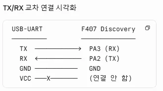
I connected them as shown above. I did not connect the VCC pin — the converter runs on 3.3V and the F407 Discovery is a 3.3V logic board, so there’s no need to supply separate power. Only GND / TX / RX are wired.
Watch the wiring direction: converter TX → STM32 RX, converter RX → STM32 TX. Since one side sends what the other side receives, they cross over in an X pattern.
The jumper cable didn’t fit into the front header
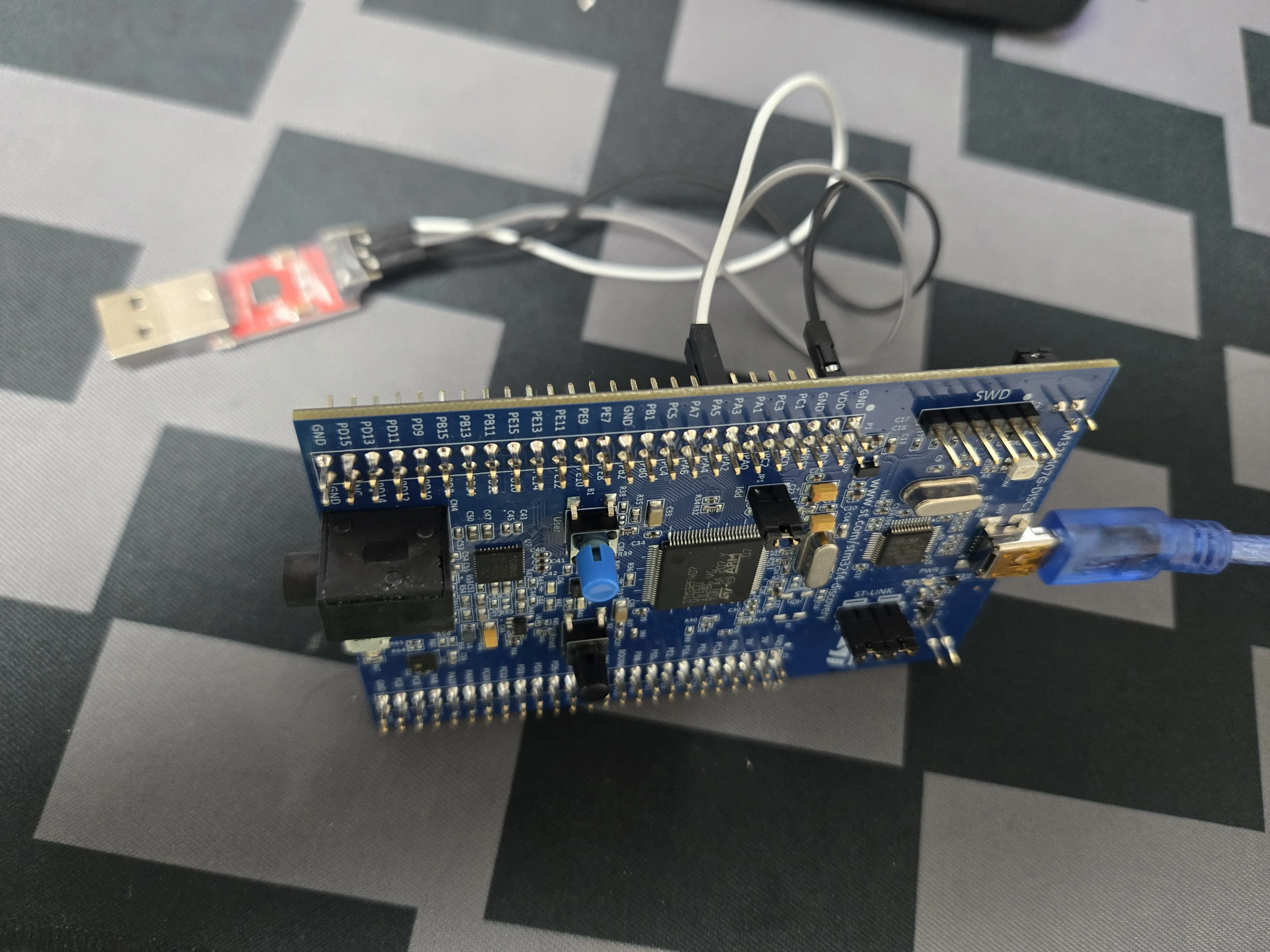
The jumper cable didn’t fit well into the front header, so I connected it to the rear one instead. The rear header seems to be the correct one for jumper cables, and the front one seems dedicated to some specific connector, but I couldn’t figure out which one (need to check later).
2. Why USART2? Why not USART3?
Before writing any code, I decided which USART to use.
Reasons for choosing USART2:
- On the F407 Discovery board it’s mapped to PA2 (TX) / PA3 (RX), which is easy to access via jumpers.
Reasons for not using USART3:
- I’m planning to keep USART3 reserved for RS485 communication. Since the AGV’s Raspberry Pi ↔ STM32 communication will go over RS485, I’m leaving USART3 open in advance.
Starting with blocking — DMA + interrupt later
There are three ways to transmit over UART:
| Method | Behavior | When it’s suitable |
|---|---|---|
| Blocking | CPU halts until transmission completes | Learning, short debug messages |
| Interrupt | Callback on transmission complete | When responsiveness is needed |
| DMA + Interrupt | Transmits directly from memory without CPU involvement | Large volume / high-frequency communication |
Blocking is enough for now. Sending a short message like “Hello AGV” once per second is fine even if the CPU stalls briefly. I plan to introduce DMA for RS485 communication. It becomes necessary once things get bidirectional and high-frequency.
Also, to minimize variables, I commented out the existing PWM code (the LED cycling part from the last post). I wanted to look at only one thing at a time.
3. Enabling USART2 in CubeMX
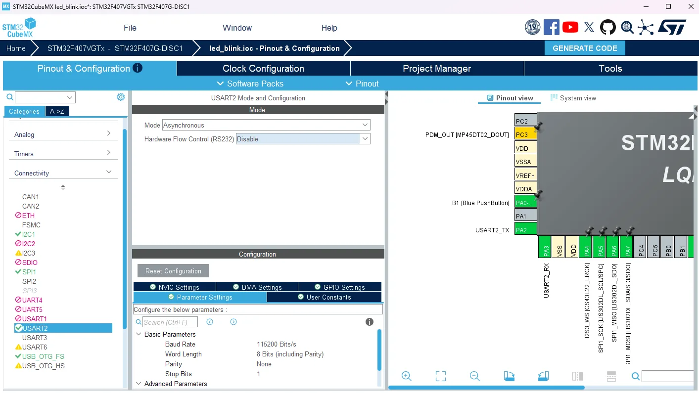
- Mode: Asynchronous
- Baud rate: 115200
- Word length: 8 bits
- PA2 → TX, PA3 → RX auto-assigned
After configuring this and generating code, I can transmit with HAL_UART_Transmit().
4. Bringing up a serial console inside STM32CubeIDE
I could check the results with a separate program like Putty, but since I’m already using STM32CubeIDE, I looked into how to bring up a console right inside the IDE.
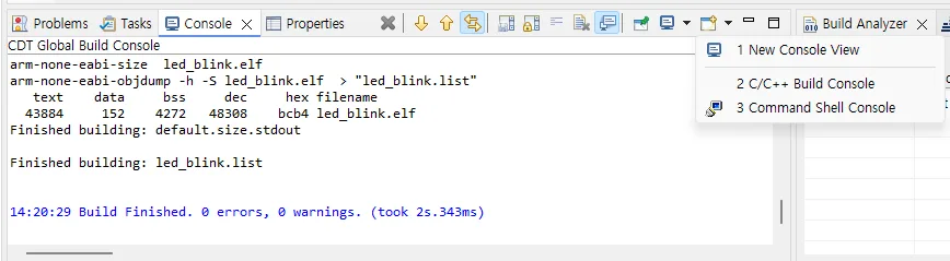
Steps:
- Click the ”+” dropdown in the Console tab
- Select Command Shell Console
- Change Connection Type to Serial
- Specify the COM port assigned to the UART converter (visible in Device Manager)
- Match the baud rate, word length, etc. to the board’s settings
5. Result — confirming message reception
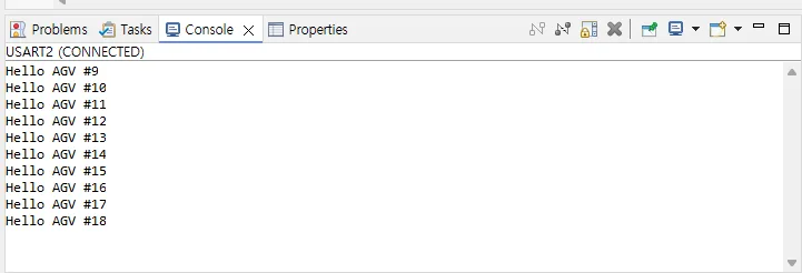
The Hello AGV #N messages came through nicely every second. The STM32 → converter → USB → PC path is verified.
I wanted to do more, but I need more cables to arrive, so STM32 work stops here for today. Next time I’ll expand to bidirectional communication (receive + echo).
6. ROS2 launch file — bringing up multiple nodes at once
On the Raspberry Pi side, I worked through an additional ROS2 example. What I learned today: launch files.
What is a launch file
A tool for running multiple nodes at once. Up until now I’ve been bringing up nodes one at a time with ros2 run, but in a real system more than 10 nodes need to run simultaneously (motor control / sensor input / path planning / safety circuit / logging…). Launching them one by one would require 10 terminals.
A launch file bundles all of that into a single file.
from launch import LaunchDescription
from launch_ros.actions import Node

def generate_launch_description():
    return LaunchDescription([
        Node(
            package='my_agv_pkg',
            executable='talker',
            name='talker_node',
            output='screen',
        ),
        Node(
            package='my_agv_pkg',
            executable='listener',
            name='listener_node',
            output='screen',
        ),
])- Inside
LaunchDescriptionyou put a list of actions (nodes) to run - Each node is given a package name / entry point name / runtime node name
output='screen'prints logs to the terminal
Trial and error — I was editing the local file
Maybe because I typed the code out instead of copy-pasting, I hit an error while running it.
launch file not foundAt first I thought, “what’s going on?” — turns out I was editing the file on the local environment (Windows) instead of the SSH environment (Raspberry Pi). Felt kind of dumb, but it’s a mistake anyone makes at least once.
It’s easy to get confused when VS Code’s Remote SSH tab and local tab are open side by side. Next time, I’ll check the hostname in the file path before starting work.
Result — running two nodes simultaneously
I moved the edits back to the Raspberry Pi side file, then built and ran it.
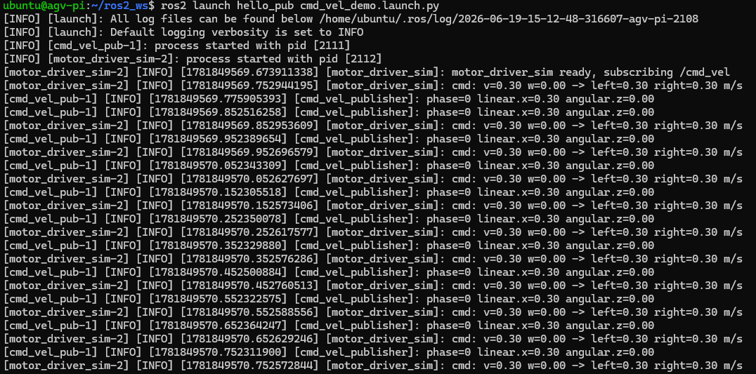
Confirmed both nodes coming up at the same time. Later I plan to bundle micro-ROS (a ROS client that will run on the STM32) together with the Raspberry Pi nodes into a single launch file. Apparently this is the standard approach for deploying real systems.
What I did today
- Wired the USB-UART converter to the STM32F407 (skipped VCC since it’s 3.3V logic)
- Chose USART2 (reserved USART3 for RS485)
- Blocking-mode transmission at a 1-second interval (
HAL_UART_Transmit) - Confirmed serial reception using STM32CubeIDE’s built-in Command Shell Console
- Ran talker + listener nodes simultaneously with a ROS2 launch file
Next steps (next Monday)
- F407 bidirectional UART communication — receive + echo
- Setting up micro-ROS agent + client — letting the STM32 act as a ROS2 node directly
- Wiring the motor driver once more cables arrive
Retrospective
It feels like I’m just learning without making much progress. A big reason is that embedded parts don’t arrive on time, but the pace is so different from when I was building web services solo that it feels a bit awkward.
One thing is different though: instead of an AI agent changing the code, I’m the one typing out what’s been written. Just that feels like it helps with learning. Passing it through my keyboard once more seems to make it stick in my head better.
I’m not feeling great today, so I’ll stop here. Resting over the weekend and continuing on Monday.
Collection of trial and error
When the COM port doesn’t show up
Sometimes when you plug in the USB-UART converter, the COM port doesn’t appear in Device Manager. → Install the driver for the relevant chipset (CP210x / FT232 / CH340, etc.) so it gets recognized.
”Termination of previous launch did not complete successfully”
The build succeeded, but this error appeared when trying to flash. Fix:
- Force-quit the ST-Link debug server (
ST-LINK_gdbserver.exe) from Task Manager - Unplug and reconnect the USB cable on the STM32 dev board
- Flash again
This happens when ST-Link is left in a state where it failed to clean up a previous debug session.
Things to study further
1. Trade-offs among the three STM32 UART transmission methods
- Blocking (
HAL_UART_Transmit) — simple, occupies the CPU - Interrupt (
HAL_UART_Transmit_IT) — doesn’t occupy the CPU, requires callback handling - DMA (
HAL_UART_Transmit_DMA) — for large volume/high frequency, transfers directly from memory - Why DMA + interrupt becomes almost essential in an RS485 multi-drop environment
- Callback flow on top of HAL (
HAL_UART_TxCpltCallback, etc.)
2. The exact difference between USART and UART
- UART = Universal Asynchronous Receiver/Transmitter — asynchronous only
- USART = Universal Synchronous/Asynchronous… — can add synchronous mode
- STM32’s “USART” peripheral supports both, but usually only Asynchronous mode is used
- Example use of synchronous mode (similar to SPI form)
3. What a baud rate of 115200 means
- 115200 bits transmitted per second
- Effective data rate = baud × (data bits / total bits) — accounting for start/stop bit overhead
- At higher speeds (921600, 1Mbps, etc.), cable length and noise start to matter
- How clock accuracy (HSI vs HSE) affects baud rate error
4. Going deeper into ROS2 launch files
- Arguments and substitutions — injecting values at runtime
- Conditional execution —
IfCondition,UnlessCondition - Group actions — namespace isolation, lifecycle control
- Differences between XML / YAML format launch files and Python format
- Official ROS2 Launch tutorial
5. micro-ROS — the mechanism by which the STM32 becomes a ROS2 node
- The core topic of the next post
- The micro-ROS agent (PC/Pi side) ↔ client (MCU side) structure
- The micro-XRCE-DDS protocol (a slimmed-down version of DDS for embedded use)
- The flow of publishing ROS2 topics directly on top of STM32 + FreeRTOS